The Surlon Power 4S 150A LiFePO4 BMS is a protection and balancing board for packs built from four lithium iron phosphate cells in series. Four 3.2 V cells give the 12.8 V nominal pack that the market sells as a 12 V lithium battery, so this board is the control layer inside 12 V replacement batteries, 12 V solar and backup packs, and the equipment builds that used to run on lead-acid.
A lead-acid battery leans on its charger to stop at the right point. A lithium pack has to protect itself. The board measures each of the four cells, holds them in balance, and opens the charge or discharge path when a cell, or the pack as a whole, leaves its safe window. Pack assemblers fit it because the protection then travels with the battery; equipment makers fit it because a 12 V product can run on lithium without the field failures that come from an unprotected string.
This is a board rather than a finished battery. It arrives without cells, wiring or enclosure, and it is meant for someone who can read a wiring diagram and check a tap voltage with a meter. That is the normal way boards in this class are supplied to pack builders, and the reason a battery BMS solution provider treats the documents as part of the board rather than an extra.
If you are building a complete 12 V battery rather than a conversion, the same four-cell configuration is available as a finished pack in our 12.8 V replacement range, so you can choose between assembling around this board and buying the battery ready-built.
| Board format | 4S protection and balancing board |
| Chemistry | LiFePO4 |
| Nominal pack voltage | 12.8 V (12 V class) |
| Current class | 150 A |
| Cell balancing | Included |
| Over-charge protection | Per-cell cut-off and release |
| Over-discharge protection | Per-cell cut-off and release |
| Over-current protection | Set for the 150 A class |
| Short-circuit protection | Included |
| Temperature protection | Included; sensing and cut-off points confirmed per revision |
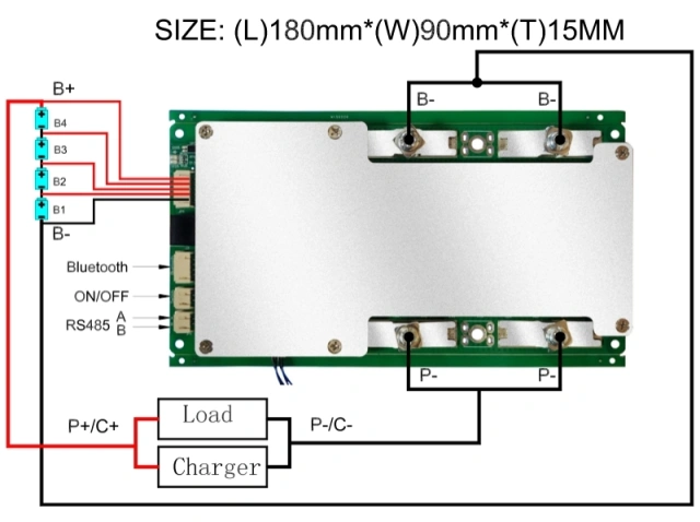
| Sense connections | Four cell taps plus pack negative |
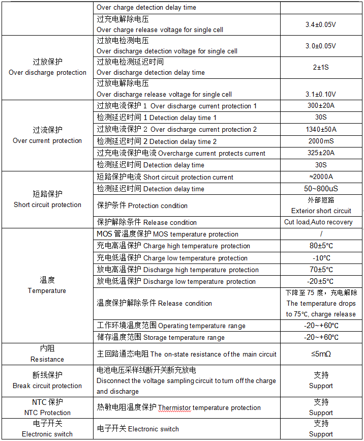
| Documentation | Wiring diagram, threshold table and dimensional drawing |
A current class is a ceiling, not a promise that the board will pass 150 A all day. Two figures matter and they are not the same: the continuous current the board can carry while staying inside its temperature limits, and the peak it will tolerate before protection trips. Ask for both, with their durations, for the revision you are buying, and design the pack around the continuous figure rather than the headline number.
At a nominal 12.8 V, a board of this class sits in the region of 1.9 kW of throughput. That is where 12 V inverters, DC compressors, trolling motors and small traction drives live, and it is the reason the higher current class exists at all. If your steady draw stays comfortably under 100 A and your surges are brief, the 4S100A board is often the tidier fit; if you run near 100 A for minutes at a time, or your start-up current sits well above it, the headroom of the 150 A class is what you are buying.
Do not choose between boards on the badge alone. Two boards carrying the same number can behave differently at the trip point depending on detection delay, thermal design and the size of the switching devices. Compare the protection tables, including release behaviour, against your real duty cycle.
The board is only one part of the current path. Cable cross-section, connector rating, fuse placement and terminal torque all have to support the same figure, and a board of this class will not make a pack built from small cells safe at that draw — the cells have their own continuous current limit that has to carry the load too.
Inrush is what actually trips protection boards in service. Motor start-up and the capacitor bank inside an inverter can draw many times the running current for a fraction of a second. If your load behaves that way, plan a pre-charge step or send us the load profile so we can review it against the board's trip behaviour before you commit.
| Board | Configuration | Current class | Typical pack voltage | Recommended fit |
| This board | 4S | 150 A | 12.8 V | 12 V builds with higher draw or long near-limit runs |
| 4S100A | 4S | 100 A | 12.8 V | Standard 12 V builds with modest continuous draw |
| ESS 16S100A | 16S | 100 A | 51.2 V | 48 V storage and backup packs |
| ESS 16S200A | 16S | 200 A | 51.2 V | Higher-current 48 V storage and backup packs |
Send the pack you are building, not just the part name. The useful brief is short: four LiFePO4 cells in series, the continuous and peak current of the load, the charger model and its charge profile, the space you have for the board, the cable length and connector you want on the sense leads, and the quantity and date you are working to. With those details we can confirm the right revision, or tell you honestly that the smaller board is the better match.
Customisation is discussed per project. Cable length, connector type, labelling and how the boards are packed are the usual starting points. Which of these are available for this model depends on the configuration, so the answer is confirmed in the quotation rather than assumed here.
Sample availability, minimum order quantity, lead time, payment terms, packing and freight are quoted for the specific order. Ask your sales contact and they will confirm the current terms for your destination and quantity — nothing on this product replaces that quotation.
For distributors and private-label brands, we act as a battery BMS solution provider rather than a box shipper: the revision, the documentation set and the labelling convention can stay with you across repeat orders, so a board you qualified last year is still the board you receive next year.
Technical questions reach the people who build the packs. Our engineering group in Shenzhen reviews your device's voltage window, load profile, enclosure space and charger before proposing a configuration; our sample group then builds units so you can validate fit and runtime before production. Cell selection, BMS design and pack assembly stay in-house, with quality checks in process and at final inspection, and a documentation team handling certificates, test reports and shipping papers. When a unit behaves unexpectedly in the field, our engineers help trace the fault and advise on installation and commissioning.
The 4S 150A LiFePO4 BMS is configured around lithium iron phosphate per-cell windows, so its cut-off and release points suit LFP cells. NCM and LTO strings sit at different voltages per cell and need different thresholds — send us the chemistry and the cell datasheet before you commit, and we will confirm whether this revision suits or whether a different configuration is the better starting point.
A 12V battery management system with balance corrects the slow drift that builds between cells as they age: self-discharge, temperature and slight capacity differences all push the four cells apart, and balancing brings them back together, normally towards the top of the charge. That keeps the pack usable at close to its full capacity for longer. It cannot rescue a cell that is already damaged or badly mismatched, which usually shows up as a pack that still trips early after a full balance cycle.
Current class is the headline: 150 A against 100 A, which buys headroom for start-up surges and for loads that sit near the top of the smaller board for minutes at a time. It is not the only difference, and the number alone should not decide it — compare the protection tables for both, including detection delays and temperature behaviour, against your real duty cycle. If your steady draw stays comfortably under 100 A with short peaks, the smaller board is usually the tidier choice.
Not without checking it. Compare the charger's finish voltage and profile against the board's per-cell over-charge cut-off, and look for equalise, desulfation or repair modes — those push a pack above the lithium window and the board will treat them as a fault. A charger that terminates cleanly inside the window and does not restart on its own is the safe pattern. Send us the model and charging profile and we will review it with you.
Sometimes, but it is a system decision rather than a wiring one. Parallel packs need to be matched in age and capacity, share current evenly, and be protected against one pack feeding back into the other; the boards also have to behave predictably when one of them trips. Describe the arrangement and the loads before you wire it — it is better to review the plan than to find the limit in the field.
Yes. We build 4S boards for 12 V packs and 16S boards for 48 V storage packs, and we work as a battery BMS solution provider for pack builders who need the board, the pack and the paperwork to line up. If your product range spans 12 V and 48 V, mention both at the start so the two builds can share documentation conventions and connector choices.